
And we’ve reached the end, for now. The last piece of designing this truss, after philosophy, schematic design, 2D truss analysis, 3D truss analysis, and looking at the difference between not-real line elements and actual elements is fitting the connections together. This was more difficult with past steel structures, like this bridge, because the designers didn’t have welding. A real-life, three-dimensional structure with steel members of non-zero cross-sectional dimensions has a space problem at its joints: everything has to fit into a small space with enough of a connection to transfer load. If you have the ability to weld the joints, you can imagine having a steel sphere at each joint with the members coming in from different angles welded to it. (This issue is reflected in children’s building toys, many of which use some kind of sort-of spherical nodes for joints; the Mola Structural Kit, which is a children’s toy for adult engineers, literally uses spherical magnets as its nodes.
Looking at a lower-chord joints, we see a classic example of cheating:

The eyebars of the main truss natural come together at a “point” – i.e., their axes meet at a point – but there was no way to have the wind-bracing between the lower chords of the two trusses meet at that same point. So it doesn’t, even though though it should. Forces are transferred between the lower chord and the bracing rods through a circuitous load path: from the lower chord eyebars to the pin, from the pin to the bolted bracket hanging down, from the bracket to the deck beam, and from the deck beam web to the wind bracing. The wind bracing axes cross in line with the main truss node if we measure along the length of the bridge, but they’re something like 8 inches too low and maybe 6 inches inboard of where they should be. That means there is local bending in all of the members I just listed so as to transfer the forces, and in a theoretical line-drawn truss, local bending does not exist. The horror! The bracing rods could be moved higher and have their intersection moved outward, but there is no good way to attach those rods to the pin that is the center of the connection. The easier route, and the one taken here, is to simply design all of the pieces in that load path for the local bending. That is not “pure truss” but it works and it’s not that difficult.[efn_note]”It works and it’s not that difficult” could be my design mantra.[/efn_note] Let’s look at an upper chord connection:
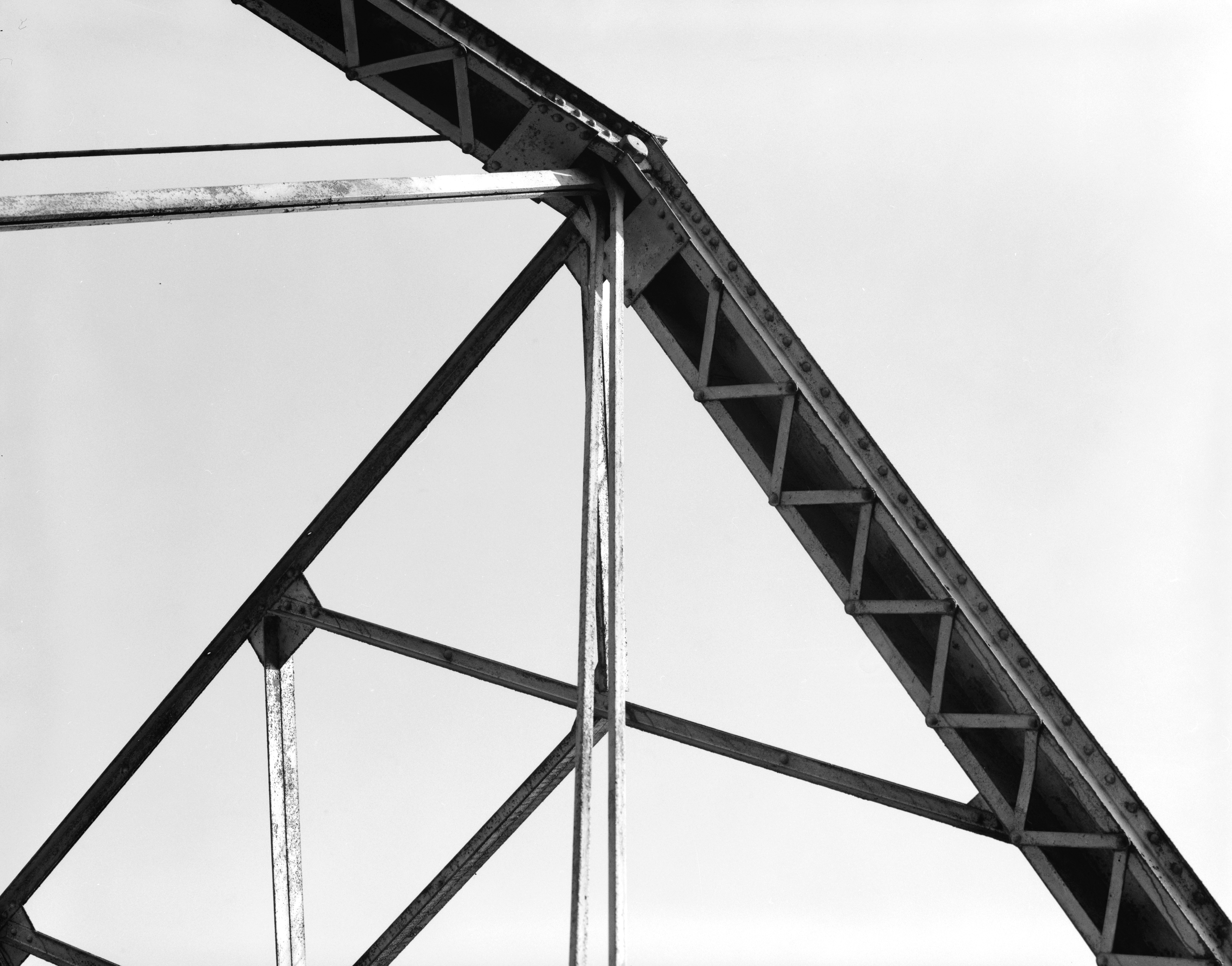
The built-up box upper chord turns out to be a great place to hide a pin. The top-plane wind bracing is running into that box a long distance away from the joint, so the same kind of local bending issues will apply here. The portal bracing shows another version of yesterday’s issue: technically that’s truss bracing, but the double-angle members are riveted to the gusset plates, so the theoretically pinned connections have some inescapable moment capacity.
After a week of looking at this bridge, what do we have as a conclusion? The physical object differs in a lot of ways, some big and some small, from the abstract model. But analysis based on the abstract model is good enough and provides a workable design. If nothing else, I hope that serves as an antidote to any belief that structural analysis and design is especially precise.
You must be logged in to post a comment.