Speaking from my own experience, engineers learn about detailing entirely through work. I was taught almost nothing about the topic in school – I barely heard the word in school – and I’ve taught it to a lot of younger engineers who did not learn it in school. Detailing is the design process by which the tidy line diagrams that make up analytical models are translated into physical reality: beams, columns, braces, and other pieces of structure that have physical dimensions, that have to be assembled by actual people using actual tools, and that have to transfer the expected forces from piece to piece in the manner that the model assumed. Here’s a detail built around 1905, from the Fulton Street station on the Lexington Avenue subway. This station was part of the first expansion of the IRT subway south from the Brooklyn Bridge and City Hall stations, which opened the year before.

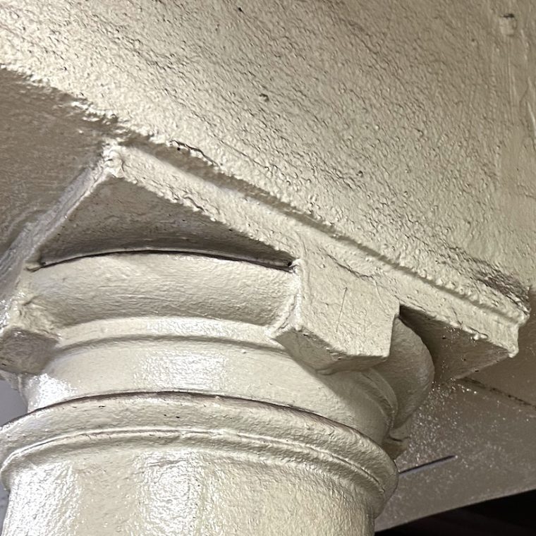
I was standing on a platform more or less facing the tracks – the tracks are the poorly-lit area, and the brightly-lit area beyond that is the other platform. The beam that starts at the upper right corner and runs down to the lower portion of the left edge is part of the roof and is above the edge of the platform, the round column is set back maybe a foot from the platform edge, and the girder that runs from the upper left over the column is perpendicular to the tracks and its left end is supported at the outside wall of the station.
The column is cast iron – there are cast iron columns in the underground IRT stations built before 1910 or so, but not elsewhere in the subway system. The girder and the edge beam are both double steel I-beam sections partially encased in concrete, as can be seen to the right of the column. Those dark lines are the gap between the bottom flanges of the two beams in both the edge beam and the girder. There are a lot of steel columns nearby – between the tracks and at the outside walls of the station – so I’m not sure what the point of using cast iron here was. Maybe to save a few dollars. Cast iron columns are not meant to carry any bending moment, just compression, and they can be difficult to connect to with large loads, so having the girder simply run over the top of the column solves some problems: any connection bolts will not be carrying the gravity load from the girder, and the over-running girder can be assumed to bear evenly on the column top.
The load path is that the roof over the platform and over the tracks rests on the platform edge beam, which is supported by the short cantilevered end of the girder, which is supported by the column. You can see that the girder extends out to the far (track) side of the edge beam, so the edge beam is not continuous and has a steel-to-steel connection to the girder. Then the girder sits on the column. Note that we don’t see any vertical-axis bolts to connect the bottom flanges of the girder to the column top, but a common detail with cast iron columns was a “pintle” – a narrow vertical extension cast with the main column – extending up from a column top. If there’s a pintle here between the two pieces of steel that make up the girder, we wouldn’t see any bolts because they’d be buried in the concrete encasement.
The design issue that I-beams weren’t strong enough for the loads (stronger wide-flange beams were not yet commonly available) drove the decision to use double beams. The detailing question of how to transfer load to a cast-iron column pushed the designers to over-run the girder; the detailing question of how to transfer loads from two edge beams pushed the designers to carry the girder all the way past the edge beam.


You must be logged in to post a comment.