
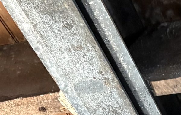
A large probe exposing a corner column on a 1910s building, from a few summers ago:

To be clear: I was standing on scaffolding looking in towards the building. The diagonal thing on the far right is a scaffold brace back to the building. My feet were a bit below a building floor level, but you can’t see the beams framing that floor as they are just below the bottom of the view.
What we’re looking at: a very ordinary column of the era. It’s a box in section, made up of two channels toed away form one another and spaced so that a rectangle that just enclosed all four flange tips would be very close to being a square. At the bottom of the building, the channels are connected with plates on the two non-channel sides of that square; at the upper floors they are connected by diagonal lacing, as you see here. Both the plates and lacing serve to tie the channels together, but the plates also add to the usable section area and to the columns’s weak-axis moment of inertia (which is, confusingly, parallel to the channel’s strong-axis moment of inertia.) If you’re designing one of these from scratch in, say, 1915, you pick a column depth (10 inches here), start with lacing and a light column, increase the column weight as you go down the building and more load is being carried, and then switch to a plated column when the load gets too high for the heaviest channels of that depth.
The plate we’re seeing is not the plated part of the column. It’s a splice. If you look at the channel facing right and count up from the bottom of the photo, you can see where the channel above and the channel below abut between the third and fourth rivet. Here’s a blow-up with contrast increased and some arrows:

Rather than try to directly connect the channels at the splice, which was annoyingly difficult to do in an era without welding, the gravity load was carried (hopefully) by direct bearing, with the splice plates ensuring alignment. The portal-method frame analysis used at that time assumed that column moments were zero at each floor (taken out by lateral forces into the floor framing), so it was okay to have splices that couldn’t carry any moment in one direction as long as the splices were near the floor levels.
Note that all of the steel is two wythes of brick (8 inches) back from the outside face of the walls. The walls are three wythes thick, but the column is encased by brick, for fireproofing, on its inboard faces. That brick pier was tied into the wall with headers, which were broken in the removal and were replaced by metal ties when the work later continued.
The loss of steel from the channels was minor and acceptable. The condition of the rivets, particularly at the outside corner, was more worrying, but some examination showed that the rivets shafts were still intact. The most disturbing thing here was the damage to the lacing, such as the upper-left to lower-right piece one down from the plastic. If the lacing fails, the channels are no longer braced properly, and the strength of the column nose-dives. So we did repair and replace some lacing plates.

You must be logged in to post a comment.