

National Geographic articles always have great pictures, and this one on the construction of Yankee Stadium is no exception. The article text tells the basic story; the best of the old drawings is, in my opinion, the 1934 extension steel diagram. (Yankees purists – which I am not – will probably prefer the architectural section through the seating and the elevation of the upper facade.)
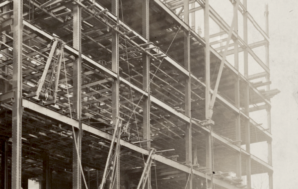
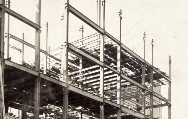
Before steel framing was used in buildings, and long before it was used for such geometrically complicated structures as a stadium grandstand, it was used for bridges. Many of the details and techniques used in steel construction were first developed for truss bridges. Many of the laborers who worked on early stele-frame buildings in both fabrication and erection of steel got their training on bridge projects. In case I’m being too subtle, one of the big steel erection companies of the early twentieth century was the American Bridge Company. (They’re still around, but has gone back to their bridge roots and no longer build building frames. However, a company that erected roughly half the steel for the Empire State Building can’t really be forgotten in a discussion of building frames.)
If you look at the steel drawing for Yankee Stadium, you’re seeing old bridge technology applied to a complicated building structure. There’s no aesthetics here: what you see is what’s holding the grandstand up. You can actually get a sense of how big the loads are in various members simply by looking at how big they are. If you look at any of the connections – Detail B, for example – you can see that the designer has carefully shown the center-lines of all of the intersecting members meeting at a point. This is necessary to prevent secondary bending moments, possibly quite large, from accidentally being created. Most of the drawing is a single cross-section through the entire grandstand structure, with grid lines A though K labelled at the bottom. This particular section, showing trusses 32 and 33 at the roof, trusses 22, 23, and 24 at the upper deck, and trusses 12, 13, and 14 at the mezzanine, takes place at locations where there are no intermediate columns. The location of those intermediate columns is obvious when you look: the concrete footing at grid line D is much larger than the other footings below the main level concrete structure, and that line coincides with the front of the mezzanine and a change in the geometry of the upper level.
As a matter of fact, two details are just barely visible to us, as 80-years-later interlopers, that were obvious to the steel workers. First, where grid line D intersects the upper deck and roof you can see, in cross-section, the big trusses that span perpendicular to the plane of the page between the D line columns that are not drawn here. In other words, the steel we see at those levels is supported by a truss in the third dimension. Second, at the far right side of the roof truss is the famous upper facade, described as “Sheet Metal”. In other words, the decorative facade was not important enough from a steel perspective to waste more space on this critical drawing.
You must be logged in to post a comment.