
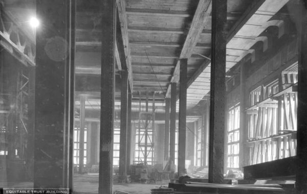
In New York, all of our metro rail is “the subway” even when it’s elevated or in an open cut. These two photos are the Brighton line – the B and Q trains – in an area reconstructed between 1905 and 1908. The retaining walls on either side of the cut are reinforced concrete and the stations are built into the walls with a mix of steel framing and concrete. For example, the bridge that carries Cortelyou Road over the cut is supported by built-up steel plate girders that project above grade between the sidewalk and driving lanes. The picture above shows the view of the wall (left) and a platform; here’s the view from across the tracks:

The steel columns support a steel beam encased in concrete. That beam serves as the track-side support for the concrete above. The bottom of the concrete is shaped like a barrel vault but maybe it is a vault and maybe it isn’t. I’ll come back to that. The top of the retaining wall – which, as the second picture shows, is literally holding up soil for people’s rear yards – is located just about in line with the crown of that vault. If you look at the far left of the second picture, you’ll see that, where the platform is more exposed to the weather, the lower (platform level) portion of the retaining wall has a sort of half-vault at the top to reconcile the two planes of wall. The lower wall curves out river the platform and then goes straight up.
So…what’s actually going on here? (In terms of structural load path, that is; what’s going on in Flatbush is the same regardless of structural engineering.) It is unlikely that the vault is really acting like a vault because vaults, like arches, develop outward thrust at the supports. There is no sign of such a force acting on the encased beams at the column line (for example, bowing or tension cracks in the track-side surface) and there’s nothing there but the beam to resist that (theoretical) force. It’s possible that the vault concrete is reinforced to make it work as a slab, which would explain the half-vaults at the uncovered platform, where the reinforcing could be used to make the slab cantilever. The arguments against that possibility are (a) the BRT company (which built this station) and its frenemy the IRT company didn’t really like or use reinforced concrete much and (b) there’s no sign of damage from rusting rebar. The last two options are similar in effect and and in that both are not part of the normal world of concrete design: the vault is quite thick and the concrete could be acting as an unreinforced slab, and because of the thickness, the load from the upper wall and earth may be distributing through the concrete in near-vertical lines. The last is similar to a vault’s arching action, but takes advantage of the thickness to make the thrust lines closer to vertical.
Only the reinforced slab can be directly proven or disproven, by determining whether there is sufficient rebar there for those analysis mechanisms to work. The other three all look the same: a huge glob of concrete (unreinforced or lightly reinforced) sitting on the lower wall and the columns. It’s possible that careful investigation and analysis (i.e., not messing around while waiting for a train) would rule out one or two of those options, but it’s also possible that it wouldn’t. That’s my favorite part of this exercise: if two of the mechanisms work (by analysis) and may be present (by investigation) then as far as I’m concerned, they both do. It’s like Schrödinger’s cat applied to structure: I don’t have to choose between alternate possible load-carrying mechanisms until I want to alter the structure or until damage makes one or more of them impossible.
You must be logged in to post a comment.