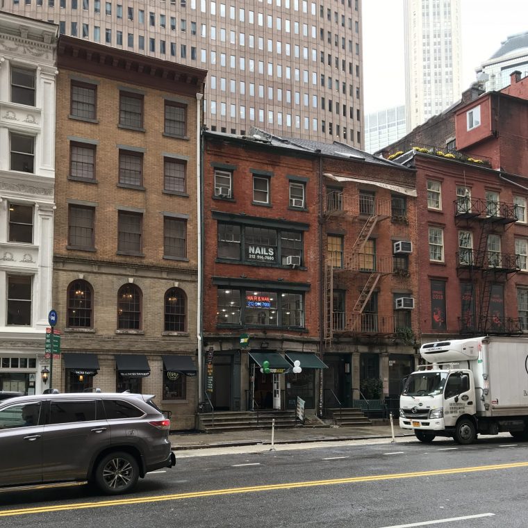
I was somewhat surprised, while writing yesterday’s blog post, to find that I had sideswiped today’s topic several times but never addressed it straight on. So today and for the next few days, I’m going to give it a shot. As I said yesterday, we don’t always know what mechanism – the combination of load path, materials capabilities, and form of stress – actually explains how something works. As a simple example, I want to look at a window lintel on the five-story tan building left of center:

The purpose of the lintel is simple: to carry the masonry spandrel panel between the lintel and the window above. The floors in this early-1800s warehouse on Water Street are supported by wood joists spanning parallel to the front facade, so the lintel is not carrying any floor load. Modern code says that we should be analyzing the front facade as a shear wall to carry wind, but realistically (this building is now and always has been sheltered from wind by its neighbors) and legally (it is grandfathered by current code as is; up until 1968, NYC code said that wind could be neglected on a building of this size and geometry) that’s not necessary.
Note that there are no headers in the pretty veneer brick. The back-up masonry that we can’t see is almost certainly common brick. The one-piece stone lintel we see may extend through both the veneer and back-up wither, but more likely is only in the veneer, and the back-up has a separate support. In any case, what’s the mechanism? What’s the structural action here? The straight lintel (and the current training of structural engineers) suggests that (mechanism 1) the stone is a simply-supported beam, carrying the load above in flexure, with maximum moment in the middle. But there are plenty of other options. The lintel is built solidly into the brick at each end, preventing easy rotation of the stone, so maybe it’s acting (mechanism 2) as a fixed-ended beam. Maybe, if we analyzed it (mechanism 3) we’d find that it’s a pair of cantilever beams that happened to be joined in the middle. Maybe we can find an arch thrust line within the stone (mechanism 4) that allows it to work as an arch; maybe we can find an arch thrust line in the spandrel panel above (mechanism 5) that means that the lintel is doing very little work. There are probably more than these five but I fell like I’ve muddied the field enough.
I haven’t analyzed this particular lintel, but I’ve done the work on a similar case and all five mechanisms worked for both stress and end conditions. In short, all five were feasible. They differ on stiffness, with the arches moving less under load than the beams. And they differ on the effect of minor changes to the masonry physicality, otherwise known as boundary conditions. If the lintel stone were cracked on the bottom, for example, mechanism 1 becomes much less workable. If the brick at the ends is in poor condition, mechanisms 2 and 3 are unlikely. If the load is greater than just the spandrel panel (if this condition exists at a window in a bearing wall, for example) the arch thrust would be too great for the end pier, and mechanisms 4 and 5 may not work.
In order to establish that the lintel “works” – i.e., that it is safe for expected loads in its current state – I need to show that one of those mechanisms is feasible (has the boundary conditions necessary for analysis) and that analyzing it shows that the material is not overstressed. It does not matter if another mechanism exists that can also cary load as long as the mechanism I’ve analyzed works.
You must be logged in to post a comment.