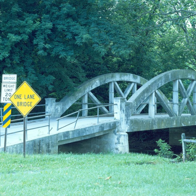
That’s the Weaverland Bridge, carrying Quarry Road over Conestoga Creek near the village of Terre Hill, Pennsylvania. (HAER says it’s it’s the Conestoga Creek, my map says it’s the Conestoga River. I have no interest in the outcome of that argument.) It’s a concrete tied-arch bridge constructed in 1916, which makes it early for a concrete bridge in the US. The sort-of-Pratt web layout is apparently also noteworthy. It’s not big: the deck is not quite 59 feet long and not quite 20 feet wide; the clear span between the abutments is less than 55 feet. It replaced an iron bridge constructed in 1870.
It’s easy to nit-pick the past in areas where we have today the benefit of vastly more knowledge. For example, the concrete mix and methods of placing concrete for the bridge both could be improved using modern standards. But those improvements are incremental and I feel like a bully discussing them. I feel less guilty when I pick on aspects of an old design that the designers knew were problematic back then. They had their reasons for ignoring known issues, but I don’t have to accept those reasons. In short, I really dislike the form of this bridge.
The pony form, with low trusses on either side of the deck is problematic for bracing no matter what the material or shape of the truss is. Iron and steel pony trusses usually have some form of out-of-plane bracing to restrain the top chord from buckling. There are clearly no such braces here. The top chord – the arch – is restrained from buckling by bending in the web members, particularly the verticals. That’s certainly possible, but it needlessly complicates the design of those members.
Reinforced concrete can be used in tension – as it is here in the diagonals and bottom chord, but doing so makes my skin crawl. The bottom chord has mixed tension and bending from gravity loading; the diagonals have mixed tension and bending from stabilizing the upper chord and incidental moments from the continuity at the ends of the diagonals. Putting aside my squeamishness, reinforced concrete cracks in tension – which is part of the necessary action to transfer the tension from the brittle concrete to the ductile steel reinforcing – and exposed cracks in a bridge seem like a bad idea.
While I’m at it, why would you make a truss in concrete? The truss form is used because it’s easy to analyze by treating the connection points as capable of transferring only axial force in the members. That easy model is pretty much true for ductile metal (wrought iron and steel) trusses. It’s not remotely true for a concrete truss with rebar continuity. As the HAER documentation makes clear, the rebar is continuous across the truss joints.

Here’s what I really don’t understand: if you are capable of analyzing and building this bridge, you are capable of analyzing and building, say, a concrete girder bridge with the same span and loading. The girders would have to be deep to work with the concrete analysis of that era, but you could easily make the girders six feet deep if you wanted. If you don’t want to have the greater deck elevation needed for a deck-girder bridge (with the deck on top), you could put the girders partly above and partly below the deck. That recreates the top-bracing problem of a pony truss, but with a shorter distance. If this was a 200-foot span, I can see not wanting to use girders, but for a big span like that the arches could be braced against each other at the top.
Permalink