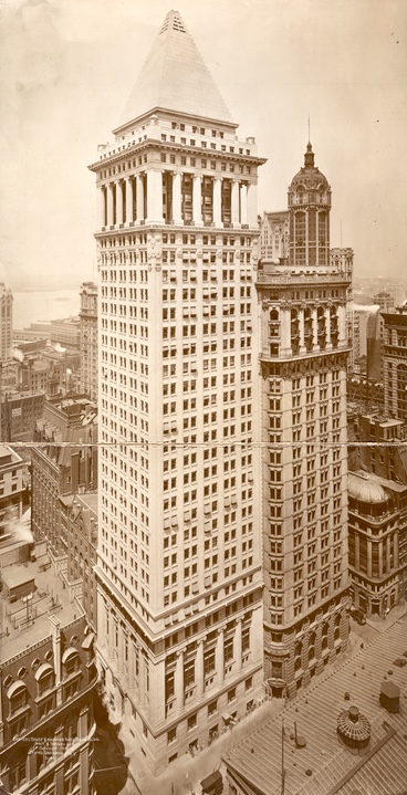
Above, Bankers Trust as it looked, completed, in 1912. (If you’re a fan of the stepped-pyramid crown and really bad movies, I suggest watching Q – The Winged Serpent. If you are not a fan of really bad movies, do not.) The construction photo album, after lovingly capturing the demolition of the previous buildings and foundation work in great detail, breezes through construction of the new building. Here are the tops of the cellar columns barely sticking up over the support of excavation bracing:

Here is a field of green shoots in spring all of the columns at the base:

Here’s the framing of the first two floors:

Here’s the full framing up two stories above grade and the columns for the huge engaged arcade above that:

And here’s the most interesting photo in the sequence, with the full framing up about ten stories:

The spandrel beam are deep built-up plate girders, leaving panel spaces between the steel that are almost square. The upper portion of this picture looks a lot like a tube frame, except that Fazlur Khan didn’t define the tube frame until the 1960s. (I’m running into a language problem here. Khan’s work on tall-building frames was remarkable and ground breaking, but I’m not sure what to call this item. He didn’t invent the tube frame, since people had built similar frames – as seen here – before him. He didn’t invent the type of analysis, since analysis can be performed on many frame forms. My best shot at it is that he defined a form of model for analysis, but the problem with that statement is that it doesn’t sound like a big deal to most non-engineers.) It was typical for a building like this – slender with a regular column grid – to have all columns “engaged” for wind resistance. In other words, each plane of columns and girders, in both the north-south and east-west directions, would be analyzed as a moment frame for its portion of the wind load, based on tributary width along the facade.
The problem with that traditional analysis is that load follows stiffness (always, in all models) and the dense grid of steel at the perimeter frames is a lot stiffer than the interior frames. But assigning load by tributary area means that the outside frames will be carrying half as much load in the model as the interior frames. Tube analysis says that you can, if you want to, neglect the less-stiff interior frames and treat the exterior frames as a tube that carries all the lateral load. It’s elegant and it works.
I know this building’s frame was analyzed in the traditional manner, but I also know that it could be analyzed as a tube and would probably work with only a few tweaks to connections.

You must be logged in to post a comment.