People usually like regular geometry, and I’d argue that architects like it more than the general public. That can create problems with buildings where the reality of construction and the reality of patterns can cause irregular geometry. The most famous example of the problem is arguably in the Doric Order, where the triglyphs are centered over the columns except at the corners, where they are at the far ends of the frieze. Look here at the illustration of the Temple of the Delians. If the end triglyphs are centered on the end columns, then there’s an odd space in the frieze between the end triglyphs and the ends; if the end triglyphs are at the ends of the frieze, then the triglyph spacing is not regular. In short: the two rules of the ornament patterns conflict, so something has to give.
This problem isn’t just about appearance. Projecting ornament was traditionally supported by having the masonry cantilever out from the body of the wall. This works as long as the amount of masonry within the wall, and the weight on it from the wall above, is sufficient to carry the cantilever overturning moment. What do you do at a corner where the projection is on both sides? I’ve seen several details used, and they’re mostly bad.
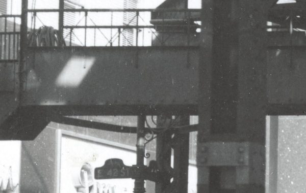
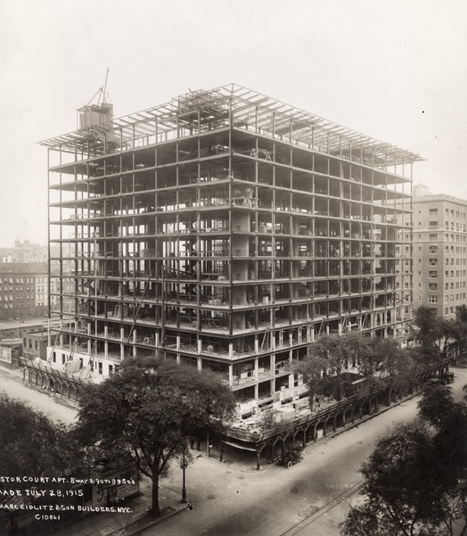
The picture above is from last week’s look at the Astor Court Apartments. The corner nearest us has Broadway on the right and the side street on the left; the steel framing for the cornice is in place and wraps the corner, as well as the corner on the other end of the Broadway facade. A steel-framed cornice does not rely on the dead weight of masonry for stability like the traditional design I described above, but it has a version of same problem: if you have a series of steel cantilevers perpendicular to the wall plane to support the projection, what do you do at the corner? The photo shows what I consider to be the best solution, and it’s elegant, too.
The flat portions of the wall have the usual steel outriggers to carry the cornice. There’s a diagonal outrigger at the corner, which also carries (a) the edge beam connecting all the outrigger tips and (b) two stub outriggers. The stubs almost certainly don’t work as cantilevers, because it would be incredible to find that they have moment connections to the diagonal. (The regular outriggers don’t need moment connections because they have back-arms that continue into the behind framing.) The stubs span between the diagonal and the edge beam, and serve as local support to the corner section of the cornice.
Nicely done.