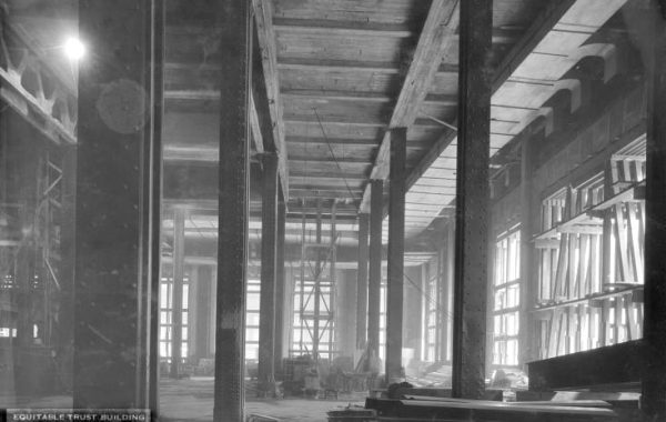
That rather artistic photo of Edgefield County Bridge No. 3 shows the top chord where it bends from horizontal (its position for most of the span) to sloped (at the end bay). The two pairs of slender rectangular-section bars coming down are the first vertical and the first web diagonal of this Pratt truss; the triangulated riveted angles are the portal bracing where the top chord bends. Anyway…
Everything I’ve done since Monday, when I was talking philosophy – schematic analysis, 2D truss analysis, and 3D truss analysis – has shared an abstraction: I’ve completely ignored the fact that the actual truss members have physical width and depth. When I perform truss analysis, I draw the truss as a line diagram, as if every member was hair-thin. Everyone I know draws trusses the same way when looking at this kind of analysis. It’s not laziness on our part, it’s because that line diagram is an accurate representation of the theory used in the analysis. The assumptions inherent in, say, the theory of joints are accurately expressed by a line diagram. For example, the theory says that the members don’t carry any bending, so they need not have any bending stiffness or strength.
In some ways, we adapt reality to the theories we use. We make sure, in this kind of truss, that the main axes of the different members meet exactly at a point at each joint, to avoid creating inherent secondary bending stresses. The use of eyebars that can (in theory, barring rust, excessive paint, or unexpected friction) rotate freely around the pin connections is an attempt to create in physical reality those perfect tension-only members in the line diagrams.
In some ways, we can’t. As I mentioned a couple of posts back, the design of steel members in compression is largely controlled by buckling, so there is a limit as to how slender we can make the compression members: most[efn_note]The first vertical at each end is in tension, because no diagonal connects at its bottom end, so all that it is doing is halving the span of the bottom chord from the abutment to the first “normal” connection with a vertical and a diagonal. Draw the force diagram, it’ll all make sense.[/efn_note] of the verticals and the top chord. The built-up-box top chord is a complex assembly with significant bending stiffness and strength, which deviates from the abstraction. Even worse, the top chord is continuous through the connections[efn_note]Because it’s much easier (read less expensive) to build that way.[/efn_note] so it will be carrying bending moments. After all that trouble (three whole blog posts!) the physical reality of the truss seems to have destroyed our previous work.
There are different ways of explaining why this is actually okay. I like to visualize what happens as a series of cartoons, like Ikea assembly instructions. You’ve got the bridge that we analyzed using line-drawing analysis, assuming real hinges at the joints, but in reality the top chord is continuous from end to end. Let’s say, for the sake of argument, that the dead load of this road bridge is half of the total gravity load, and vehicles on the deck are the other half. The bridge is built with shoring, so it’s unloaded, and then on a windless day, like a magician pulling the tablecloth out from under the flowers, the shoring is removed in an instant. The bridge has half its gravity load, so it immediately starts to deflect down in the middle. The diagonals and bottom chord go into tension, the verticals and top chord go into compression…but the top chord doesn’t act right. It’s stiffer than it should be, so it doesn’t rotate properly at the joints, and it’s got bending moments in it. They’re probably not all that big: the truss as a whole is much, much stiffer than the top chord, so if we look at the chord spanning like a beam, it won’t attract much of the load. But what if the bending moments are high? Steel is an elastic-plastic material: stress and strain are linearly related up to the yield point, and then you get quite a bit of strain with little or no additional stress. That means if you overload a steel beam in bending and it’s braced against buckling, it will develop plastic hinges. In other words, if the bending moments that we didn’t include in our analysis are too high for the top chord, it will create its own hinges and start acting more like our model. The accidental overstrength will resolve into the condition we wanted in the first place. The American Institute of Steel Construction coined a beautiful phrase to describe this, decades ago: “non-elastic but self-limiting deformation.”
I could keep this topic going for a month, but will wrap it up tomorrow by looking at the mismatched geometry in the connections.