
The truss bridges that I’ve been talking about on and off for the last year or so have had trusses that are mostly pin-connected, with eyebars of some kind used for the truss members. The small road bridge above, the 1914-1995 Bert Parsons Bridge over the Fisher River in Chippewa County, Wisconsin, looks a lot like them, but its design contains an important advance in the philosophy of steel design: the joints are riveted and bolted even though the truss was designed as if the members were pin-ended.
The HAER documentation refers to this as a Pratt through-truss but there’a bit of ambiguity. Most Pratt trusses have extra diagonals running “the wrong way” (i.e., in the compression direction) in some panels, and in this case they’re present in the interior pair of the four square panels. So you could call it a Warren truss with extra diagonals or a Warren/Pratt hybrid with, in my opinion, close to the same accuracy as calling it a Pratt truss.

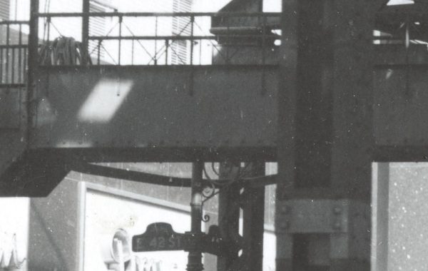
You can see the top-chord and wind-bracing connections there; here’s a bottom-chord connection:
The bottom chord, diagonals, and vertical are all bolted or riveted to the sort-of-diamond-shaped gusset plate, and the deck girder is bolted to the bottom extension of the vertical. (The combination of bolts and rivets suggests shop riveting and field bolting.)
These trusses were still basically designed as pin-jointed: as trusses rather than frames. How do you reconcile that with these big gusset plates? Steel has a number of interesting properties, one of which is “elastic-plastic” behavior. Up to a point, steel exhibits linear elastic behavior: its elongation or shortening under tension or compression load is linearly related to the amount of load. Put twice the tension load on a hanger, it stretches twice as much. After that point (the yield point) it behaves almost perfectly plasticly for a while: it stretches or compresses with almost no extra effort. Eventually it gets more difficult to elongate or shorten the piece again (strain hardening) and that’s a prelude to failure. You can use the elastic-plastic effect to your benefit in various ways, and rigidly-connected trusses are a good example.
Say, for the sake of argument, that the end connection of the paired-angle tension diagonal was strong enough to provide full moment fixity, the opposite of the freely-rotating pin that is used in the truss model. The combination of stresses from the bending moment and tension will either exceed the yield point stress or it won’t. If it doesn’t, we don’t care, but it likely will: the angles aren’t particularly strong or stiff. If it does overload the angles, the steel at the most highly stressed edges will act plastically and yield, which reconfigures the angles a bit by allowing their ends to rotate. That tends to reduce the bending stress and at some point that local yielding stops because the combined stress drops back below the yield point. The AISC specification used to have a beautiful phrase to describe this: plastic but self-limiting behavior. It allows the designer to compartmentalize the overall truss behavior (which assumes pin-ended members) from the local connection design.
This is a trick of modeling – we are deliberately misrepresenting reality in the truss model (by saying that the members are pin-ended) because (a) it makes analysis simpler and (b) the properties of steel will save us from any negative consequences of that misrepresentation. This trick, and other like it, are an integral part of structural design, and provide a good counterargument to the idea that engineering is just applied physics. Design is a separate discipline from applied math, and that’s good because it allows us to take shortcuts that prevent the design of ordinary structures from being prohibitively difficult and expensive.

Permalink