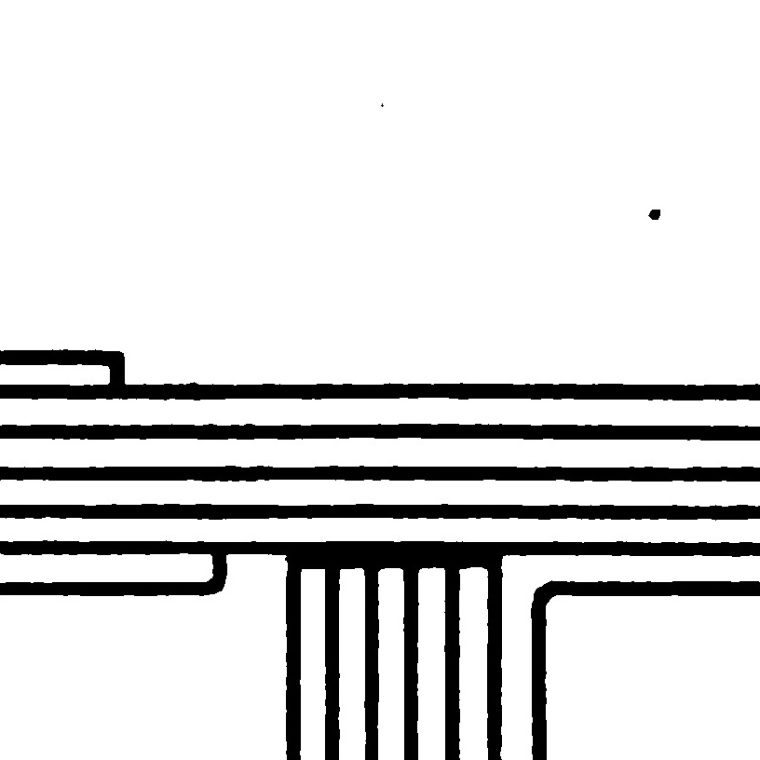
That’s an illustration from a 1913 article called “Engineering Design Of The Woolworth Building” from The American Architect. That’s the design of the most heavily-loaded columns in the building, below the tower. To put it in perspective, that built-up column, composed of plates and angles less than an inch thick, is something like 3 feet by 3½ feet in floor area, and with a cross-sectional area of 700 square inches of metal, weighs almost 2400 pounds per foot of length. That’s a big column even by today’s standards, in part because of the more conservative building code used at the time.

The article goes into the issues in assembling this, at least superficially. The rivets were an inch in diameter and up to 5¼ long between the heads. Since rivets can only connect two parallel planes of steel, the angles are there mostly to allow the connections to turn the corners between the flange plates (top and bottom of the picture) and the three sets of web plates. I say “mostly” because the four pairs of angles on the horizontal centerline of the column don’t serve that purpose. I suspect that the two pairs on the outer web plates, that create little tabs on the far left and right, are there to provide connection points for beams or girders to fasten to. The two in middle are just odd. They add compressive area, sure, but they add it close to both neutral axes, where it’s least effective. Adding the same area in the form of a couple of more plates in the outer web plates would have been better…unless the rivets were getting too long to be trustworthy. The little plate on top, looking like a pointy hat, and the two extensions of the flange plates on the right are, I’m pretty sure, places to attach a hook or cable to lift these monsters during erection.
Any time you have a big built-up section, the question arises of how to actually assemble it. That’s shop work, so it was a bit easier than field riveting, but it’s quite easy to draw something that can’t physically be built. In this case, the easy (i.e., obvious) part of the process is that the web plates would be riveted together into composite webs first. I’d guess that the angles that connect the webs to the flanges were part of the web assemblies. The flange plates might have been pre-assembled into flanges, or the rivets that run through the flanges to the angles on the web plates may have been doing double duty to hold the flanges together. But if you look at clearances, there are some bad angles you had to hold either the rivet hammer or the backer-up at:

It’s a long angled reach to the center-web connection, and it’s a tight fit to the side web connection because of those protruding steel angles. I expect the shop drawings had notes about sequencing to prevent – and I say thing with absolutely no experience of having done so – having to take your IKEA furniture apart because you put a piece in wrong and can’t finish assembly.


You must be logged in to post a comment.